
- MPU 6050 ARDUINO CAMERA GIMBAL INSTALL
- MPU 6050 ARDUINO CAMERA GIMBAL GENERATOR
- MPU 6050 ARDUINO CAMERA GIMBAL SERIAL
- MPU 6050 ARDUINO CAMERA GIMBAL CODE
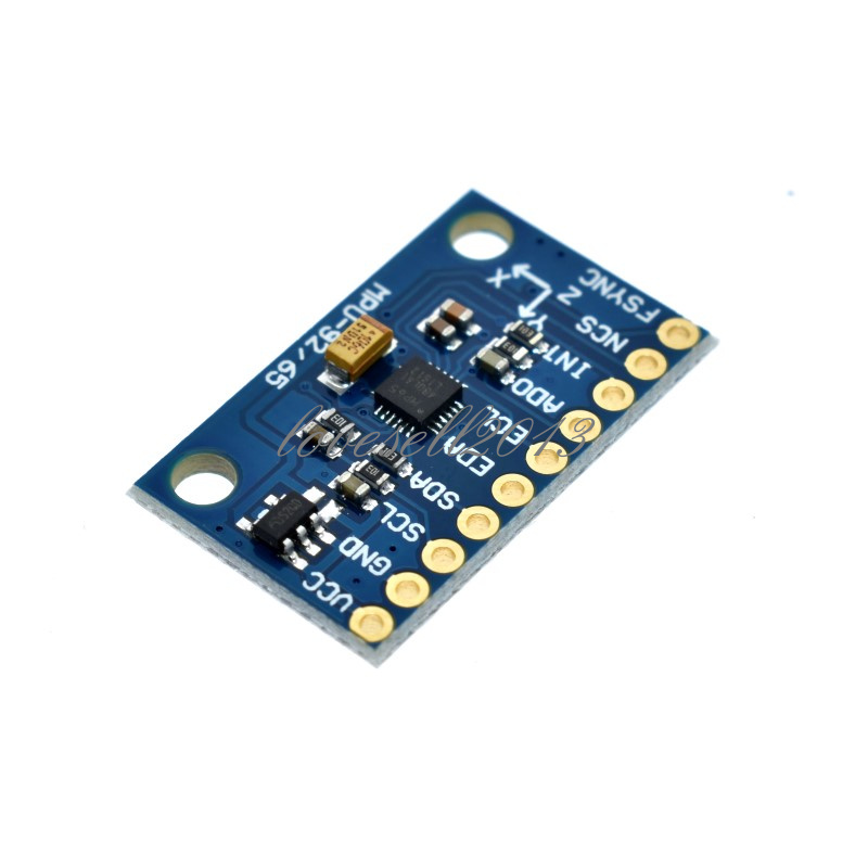
Type “ adafruit mpu6050” on the search box and install the library.Ĭode – Getting MPU-6050 Sensor Readings: Accelerometer, Gyroscope and Temperature Open your Arduino IDE and go to Sketch > Include Library > Manage Libraries. To use this library, you also need to install the Adafruit Unified Sensor library and the Adafruit Bus IO Library. In this tutorial, we’ll use the Adafruit MPU6050 library. There are various ways to get readings from the sensor. Interrupt pin – can be used to indicate that new measurement data is available Used to interface other I2C sensors with the MPU-6050 Here’s the pinout for the MPU-6050 sensor module. We can combine the information from both sensors to get more accurate information about the sensor orientation. However, it is not possible to calculate the yaw. Using the accelerometer’s values, it is possible to calculate the roll and pitch angles using trigonometry. Ideally, in a static object, the acceleration over the Z-axis is equal to the gravitational force, and it should be zero on the X and Y-axis. The MPU-6050 measures acceleration over the X, Y, and Z-axis. It senses static forces like gravity (9.8m/s 2) or dynamic forces like vibrations or movement.
MPU 6050 ARDUINO CAMERA GIMBAL GENERATOR
Serial.println(mpu.getSleepEnabled() ? "Enabled" : "Disabled") Ĭase MPU6050_CLOCK_KEEP_RESET: Serial.println("Stops the clock and keeps the timing generator in reset") break Ĭase MPU6050_CLOCK_EXTERNAL_19MHZ: Serial.println("PLL with external 19.2MHz reference") break Ĭase MPU6050_CLOCK_EXTERNAL_32KHZ: Serial.println("PLL with external 32.768kHz reference") break Ĭase MPU6050_CLOCK_PLL_ZGYRO: Serial.println("PLL with Z axis gyroscope reference") break Ĭase MPU6050_CLOCK_PLL_YGYRO: Serial.println("PLL with Y axis gyroscope reference") break Ĭase MPU6050_CLOCK_PLL_XGYRO: Serial.println("PLL with X axis gyroscope reference") break Ĭase MPU6050_CLOCK_INTERNAL_8MHZ: Serial.println("Internal 8MHz oscillator") break Ĭase MPU6050_SCALE_2000DPS: Serial.println("2000 dps") break Ĭase MPU6050_SCALE_1000DPS: Serial.println("1000 dps") break Ĭase MPU6050_SCALE_500DPS: Serial.println("500 dps") break Ĭase MPU6050_SCALE_250DPS: Serial.The accelerometer measures acceleration (rate of change of the object’s velocity).

MPU 6050 ARDUINO CAMERA GIMBAL SERIAL
Here is the logs of what we got on Serial Port.

If our wiring and hardware is proper, we should get values of each axis on Serial port for both Raw and Normalized gyroscopic change in sensor.
MPU 6050 ARDUINO CAMERA GIMBAL CODE
Once the upload is done, its time to open up the serial Monitor and observe output:ĭon’t forget to match the serial port with the baud rate we defined in start of code which is 115200 while(!mpu.begin(MPU6050_SCALE_2000DPS, MPU6050_RANGE_2G)) since our example code is ready and we understand what we did in code, its time to upload the code and view results. In this While Loop, the sensor test sequence is executed. So we begin the serial monitor in setup part. (only SDA and SCL pins change for other Arduino boards.)īasically in this example, we will see if our sensor is working so we will display the sensor data on serial monitor. This IC also has SCL SDA, which are I2C pins and XDA and XCL which are auxiliary Serial pins, we won’t use them with Arduino for this tutorial, we have AD0 which is address select between Auxiliary and Primary ports, lastly we have INT interrupt pin,Ĭonnections for our Arduino UNO and NANO are as following: Next we have few complimentary resistors and capacitors in SMD package and the most important PART the MPU6050 IC, which is a MEMS or say micro electro mechanical system, which changes voltage depending on change in axis position. So we have VCC, ground, which takes any input from 2v to 5v, since this board has a voltage regulator on board and thus supports 3.3v logic high and 5v logic high. MPU 6050 comes in a Module form, with 8 pins, but don’t worry, we will use only 4 important pins and it will be sufficient to integrate with our Arduino Board.


 0 kommentar(er)
